We are giving hereunder some comments on the relations between the unit of strain amount (×10-6 strain) and the unit of sensor output (mV/V), on a simple method of generating an equivalent strain, on the resolution of measurements and on calculations on the overall accuracies.
Measuring hint of strain gage based transducers
Relations of transducer sensitivity (mV/V) and strain amount (×10-6)
The unit of output used in strain gage based transducers manufactured by this company is "mV/V". This unit represents a rated output when an input voltage of 1V is applied to the bridge. Conversion of the output in the unit of "mV/V" into the strain amount in the unit of "×10-6 strain" can be made through the following equation:
e=(1/4)*K*E*ε
where,
K:Gage Factor
E:Bridge Input Voltage (V)
e:Output Voltage (V)
ε:Strain (×10-6)
When assume it Gage Factor K =2.00, applied voltage V =1; e = ε/2 is related, and bridge output voltage e (μV) has a double relation with strain amount ε (μstrain).
Example :
3000μstrain-----1500μV/V=1.5mV/V
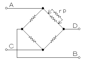
The simple equivalent strain generation method by the resistance insertion parallel to one side of the bridge.

When making operation on the Wheatstone Bridge, we have means to generate an equivalent strain by inserting a parallel resistor into one side of the bridge.
The correlations among the calibration strain (ε), the resistor inserted (rp) and the strain gage resistance (Rg) will be in accordance with the following equations when a parallel resistor (rp) is inserted into the strain gage bridge as shown in the drawing.
Rg/(rp+Rg)=K*ε
rp≒Rg/(K*ε)
The following table represents the relations between the equivalent strain and transducer outputs when a parallel resistor is inserted into one side of the bridge (120 ohms or 350 ohms). This table may be conveniently utilized for a simple checking of behaviors of strain amplifiers or for necessary compensations to be made to the leadwires of strain gages. Note however that the figures given in this table are based on the nominal value of 2.00 in gage factor.
| Transducer Sensitivity (mV/V) | 0.050 | 0.100 | 0.250 | 0.500 | 1.000 | 1.500 |
|---|---|---|---|---|---|---|
| Equivalent strain (×10-6) | 100 |
200 |
500 |
1000 |
2000 |
3000 |
| Parallel resistance for 120Ω-Bridge (kΩ) | 600 |
300 |
120 |
60 |
30 |
20 |
| Parallel resistance for 350Ω-Bridge (kΩ) | 1750 |
875 |
350 |
175 |
87.5 |
58.3 |
Combined error of Load Cell
The accuracy of the load cells shall preferably be the overall accuracies calculated out in consideration of linearity, hysteresis and repeatability in addition to various external factors including thermal properties and so on. The following equation could generally be employed as the square-root of sum of square with the certified error ranges of the respective items.
δs=[α1^2+α2^2+α3^2+(α4*Δt)^2+(α5*Δt)^2]^(1/2) (%R.O)
where,
α1:Nonlinearity (%R.O)
α2:Hysteresis (%R.O)
α3:Nonrepeatabilit (%R.O)
α4:Temp.Effect on Zero (%R.O/℃)
α5:Temp.Effect on Output (%LOAD/℃)
Δt:Temperature change (℃)
and, measurument error of force or weight in parallel connection of load cells is calculated to :
Σδs=δs/n^(1/2) (%R.O)
where,
n:Number of using load cells
In the general precision "δ" that it included the error of the measuring instrument in , it calculate for a square root of square sum of each error of the load cells "δs" and the measuring instrument "δi".
δ=[δs^2+δi^2]^(1/2)
Resolution of Load Cell
It appears that a number of questions that our users have forwarded to us regarding load cell resolutions is in an increasing tendency since the start of development of digitalization of various measuring equipment. Generally speaking, because load cells are one sort of analog sensors utilizing strain gages, the load cell as it is as a single unit does not adopt an expression of "resolution" in its technical specifications (excluding digital load cells). However, in view of higher capabilities in the field of resolution of measuring equipment in recent days, a stability in the degree of 1/10000 can be achieved in so-called high accuracy load cells (with performances of 0.05% R.O. or better *1) as far as these high accuracy load cells may not suffer from any influences from external environment such as terrible temperature changes. In other words, these so-called high accuracy load cells do have performances to carry out without problem actual measurements of phenomena within the extent from 1/100 to 1/1 of their rated capacities (*2).
*1 This refers to the case when these figures are satisfied in the specification items of the linearity and hysteresis.
*2 The extent to 1/50 of the rated capacity is regarded to be valid when the JIS B 7728 Force Calibrator is employed.
Load and installation condition of load cell
It can be said to be desirable if standing at the side of public users that the load cells and other measuring transducers in general may be improved to have better characteristics. However, no matter how high the performances of these transducers may be, it may be difficult to extract the essence of these higher performances unless the installation, conditions of measurement and so on clarifying therein the purpose of measurement and the status of accuracy required be clearly described. Contact us on mail regarding details on the method of installation and so on.
