In the measurement with strain gages, a special care should be exercised to the sensitivity deterioration to be brought about by the length of strain gage leadwires, effects caused by temperature changes, and a state of insulation of the strain gage bridge because extremely tiny voltage variations in the order of microvolts are measured through the strain gage Wheatstone Bridge employed. Several fundamental items may be hereunder treated in this paper.
Relative error of strain gage measuring
Thermal effect of leadwires between the gage and the strain-gage bridge on 1-gage 2-wire method
Even in case when a self temperature compensated strain gage is selected for the installation on a test specimen of the intended material, an apparent strain may inevitably be produced during measurements on account of the effects caused by a thermal resistance coefficient of the leadwires if they are longer than ordinary. Pay a sufficient attention to this effect especially in long term static measurements.
Measures:recommend to 1-gage 3-wire method
Correction for Gage Factor
The nominal value of the gage factor (K) is generally announced to be 2.00, but this value may be subject to a slight change depending on the configurations of the strain gage pattern, materials of the resistance elements used and so on. In these circumstances, in the event that the gage factor designation furnished on your measuring system is fixed at 2.00, a true strain value (ε) used for measurement should be calculated out with the following equation and from the indicated or measured strains (εo) obtained.
ε=εo*2.00/K
where,
K:Gage Factor (for using strain gage)
Because the general scattering of the gage factor (K) is considered to be from 1.90 to 2.10 (corresponding to the width of ±5% of the nominal gage factor), measurements on stress and strain are usually carried out without any compensation to the results obtained provided that the measuring errors have been found to be within the tolerable range of ±5%.
Sensitivity fall by the resistance of the lead wire
The resistance change coefficient to be got when the leadwires of the strain gage are extended should be understood to read "ΔR/(R+r)" instead of "ΔR/R" and the indicated strain (εo) and the true strain (ε) are expressed with the following equations, respectively.
εo=ΔR/(R+r)*K
where,
r:All resistance of the lead wire (round resistance)
and a true strain value is : ε=ΔR/R*K
R*ε=(R+r)*εo
ε=εo(1+r/R)
Remarks:
*Correct the strain error by the resistance of one way on 1-gage 3-wire method.
*Our product strain gage with normal leadwire does not need the sensitivity correction because the Gage Factor of it describe with leadwire resistance included.
Influence by the bonding up direction of the strain gage
In the plane stress state, the indicated strain "εo" of the direction where only angle θ inclined to for the main strain "ε1" can be calculated using a next formula.
εo=[(ε1+ε2)+(ε1-ε2)cos2θ]/2
Under 1-axis stress situation, ε2=-νε1, and for ε1=1, ν=0.3 (ν:Poisson's ratio)
εo=[(1-ν)+(1+ν)cos2θ]/2
εo=(0.7+1.3cos2θ)/2
Example :
The indicated strain "εo" of the direction where 5 degrees inclined to for the main stress direction come down 1% applox from εo=0.99.
Non-linearity of the Wheatstone Bridge for yield strain measurement
Please use the following equation to produce an error by the non-linearity of the bridge circuit for yield strain measurement.
ε=εo/(1-εo)
where,
ε:True strain
εo:Indicated strain
Influence of the insulation resistance
An insulation resistance when effecting strain measurements is required to be 500MΩ or more. For example, if the insulation resistance is in the neighborhood of 10MΩ and is not stable, this unstable insulation resistance is thrown into one side of the bridge in parallel and may become more and more unstable. An apparent strain in the range of around 6με (at the 120Ω bridge) is only issued as output in this case if the amplitude of resistance change is only 10MΩ. Although such a status like this looks not so problematic as far as usual measurements are concerned, there might be a possibility of the insulation resistance changing to a large extent on account of effects from the change of temperature or humidity, to which a special care should be exercised.
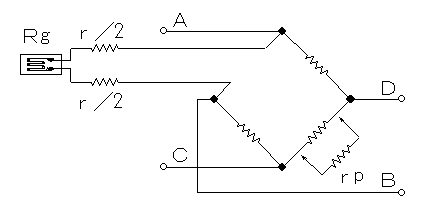
Measurement by the Wheatstone Bridge circuit on 1-gage 2-wire method

As is evident from the sketch, two ways reciprocating leadwire resistance is introduced in series into the strain gage resistance when the 2-wire connection system is employed. On this occasion, the value of the leadwire resistance (r) is expressed with the following equation:
r=ρ*l/s
where,
ρ:Electric resistivity of copper (1.8×10⁻⁶ Ω cm)
l:Round length of lead wire
s:Cross section of the lead wire
Change "εl" of the initial balance is :
εl=r/(*Rg)
where,
K:Gage Factor(G.F=2.00 nominal)
Rg:Strain Gage resistance
When this value is beyond the barance range of the measuring instrument, put resistance in one side in parallel like a figure and correct it. and, this resistance is calculated to :
rp≒Rg/(K*εl)
Additionally, If the lead wire becomes long, it cannot ignore an apparent strain by the temperature of it, and this apparent strain "εr" is output in the equation below.
εr=r*α*t/[K*(Rg+r)]
where,
α:Thermal coefficient of resistance of lead wire (3.9×10⁻³/℃ for copper wire)
t:Lead wire temperature change (℃)
εr:Apparent strain for Lead wire temperature change
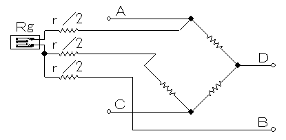
Measurement by the Wheatstone Bridge circuit on 1-gage 3-wire method

In the 1-gage method, 3-wire connection is generally employed because an effect to be caused might become considerably large when the 2-wire connection is adopted in the 1-gage method. In these circumstances, in the event that the length of the leadwire is longer than usual and if, in addition, the area of its cross section is smaller than usual, the 3-wire connection is used in the 1-gage method. If the 3-wire connection is used, the amount of resistance (r/2) is introduced not only into the strain gages but also into the neighboring side of the bridge and therefore, an apparent strain caused by the resistance change brought about by the temperature drifts can be negated. In order to better improve the situation, the leadwires led into the two sides of the bridge would have to be the same each other in their area of the cross section, length and all other specifications. The color of the vinyl coatings of the leadwire would also have better to be the same if the measuring system has to be exposed to severe direct rays of the sun. Note that, in this case, the deterioration of output to be brought about from the status of leadwires may be half of the case of the 2-wire connection because the leadwire required for the 3-wire connection will be for one way only.
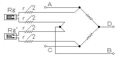
Measurement by the Wheatstone Bridge circuit on 2-gage 4-wire method

As is evident from the drawing, the leadwires are inserted in the same manner into the neighboring sides of the bridge. If these leadwires are the same each other in respect to the area of cross section, length and to all specifications, an apparent strain brought about by temperature variations can be negated and the output deterioration got in this case may become the same with that appearing when the 1-gage 2-leadwire connection method is employed.
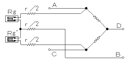
Measurement by the Wheatstone Bridge circuit on 2-gage 3-wire method

When the 2-gage 3-leadwire connection method is employed, the length of the leadwire that may exert influences upon apparent strain may become half of that when the 4-leadwire connection is used. Therefore, far better results can be expected in comparison with the case of the 4-leadwire connection being used. In addition, the range of the output deterioration may be half of the case of 4-leadwire connection because, in the 3-leadwire connection, the length of leadwire may be enough if the half length is provided.
